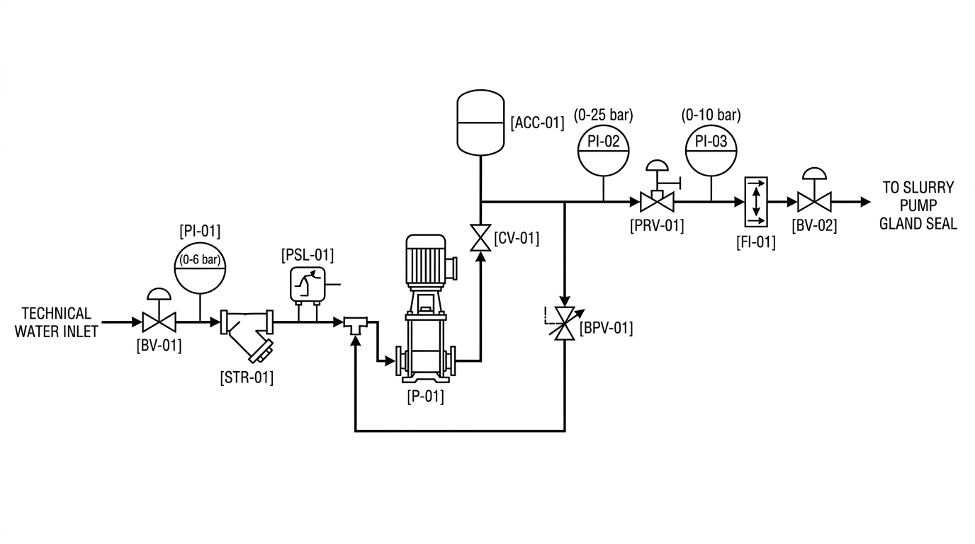

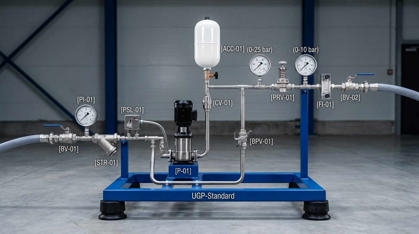
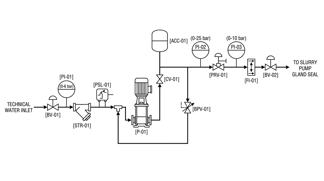
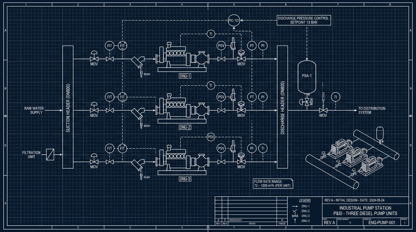







A professional 2D technical blueprint of a Piping and Instrumentation Diagram (P&ID) for an industrial gland water supply skid station, clean engineering CAD layout. Strict 2D vector graphic style, flat design, pure white background, crisp solid black technical lines, standard ISA/ISO industrial symbols, high readability. The process flows strictly from left to right: 1. INLET SECTION (Left): Text label: 'TECHNICAL WATER INLET', Manual Ball valve symbol [BV-01], Y-Strainer filter symbol [STR-01], Dry run protection pressure switch symbol [PSL-01], Inlet Pressure Gauge symbol [PI-01] (0-6 bar). Bypass return tie-in connection point located strictly AFTER the filter [STR-01] and PSL-01, but BEFORE the pump suction inlet. 2. PUMP & DISCHARGE SECTION (Center): Vertical centrifugal multistage pump symbol [P-01], Non-return check valve symbol [CV-01] on the vertical discharge line, Hydraulic expansion membrane tank symbol [ACC-01], Bypass line branching off after CV-01: contains adjustable bypass pressure relief valve [BPV-01], looping down and returning strictly between filter [STR-01] and pump [P-01] suction, Discharge Pressure Gauge symbol [PI-02] (0-25 bar) mounted directly on the high-pressure line BEFORE the pressure reducing valve. 3. PRESSURE REGULATION & OUTLET SECTION (Right): Direct-acting Pressure Reducing Valve symbol [PRV-01], Regulated Outlet Pressure Gauge symbol [PI-03] (0-10 bar) mounted immediately AFTER the PRV-01, Visual rotameter flowmeter symbol [FI-01], Outlet Ball valve symbol [BV-02], Text label: 'TO SLURRY PUMP GLAND SEAL'. Crisp black engineering typography with standard tag bubbles (PI-01, PI-02, PI-03, PSL-01, PRV-01, BPV-01, CV-01, FI-01). Strictly flat 2D schematic blueprint, clean ISO drawing standard, no 3D shading.
Free to start · Generate videos and images with AI in seconds