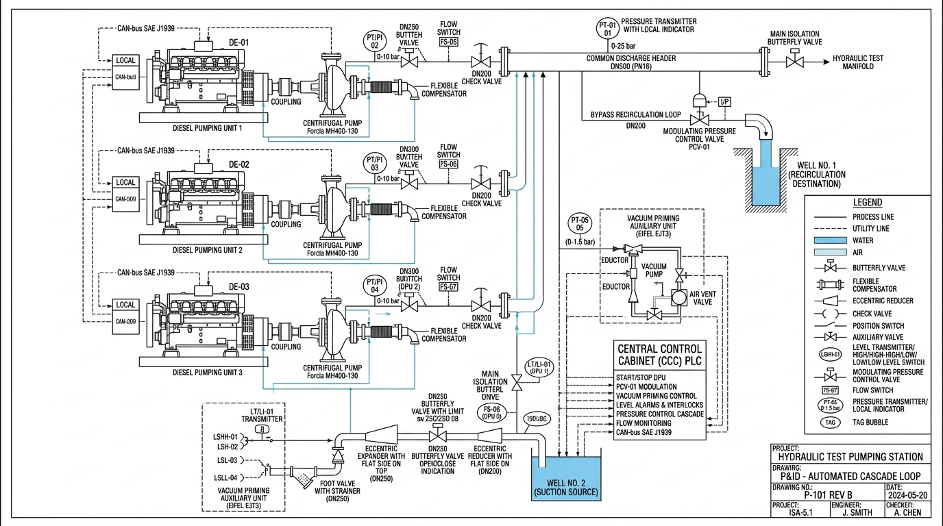


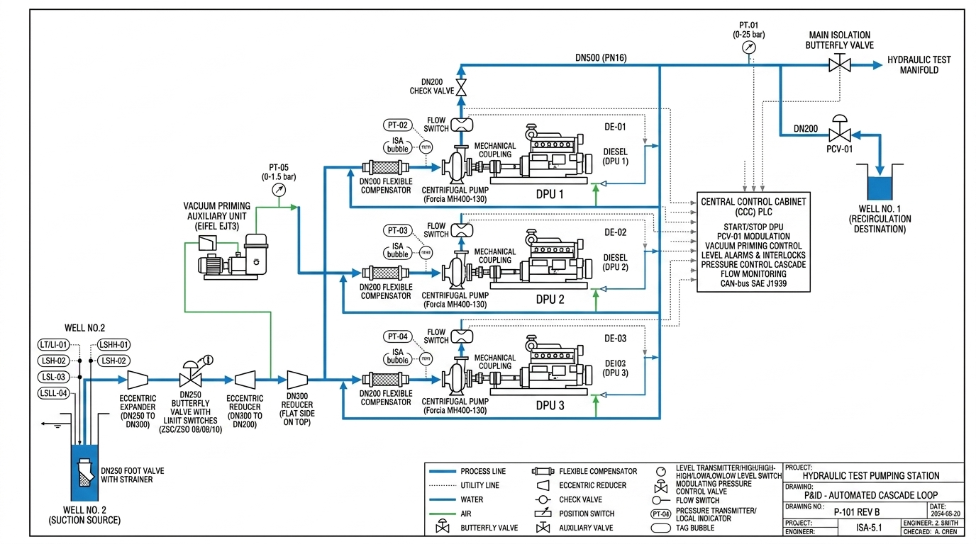
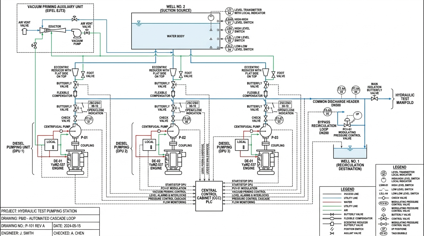

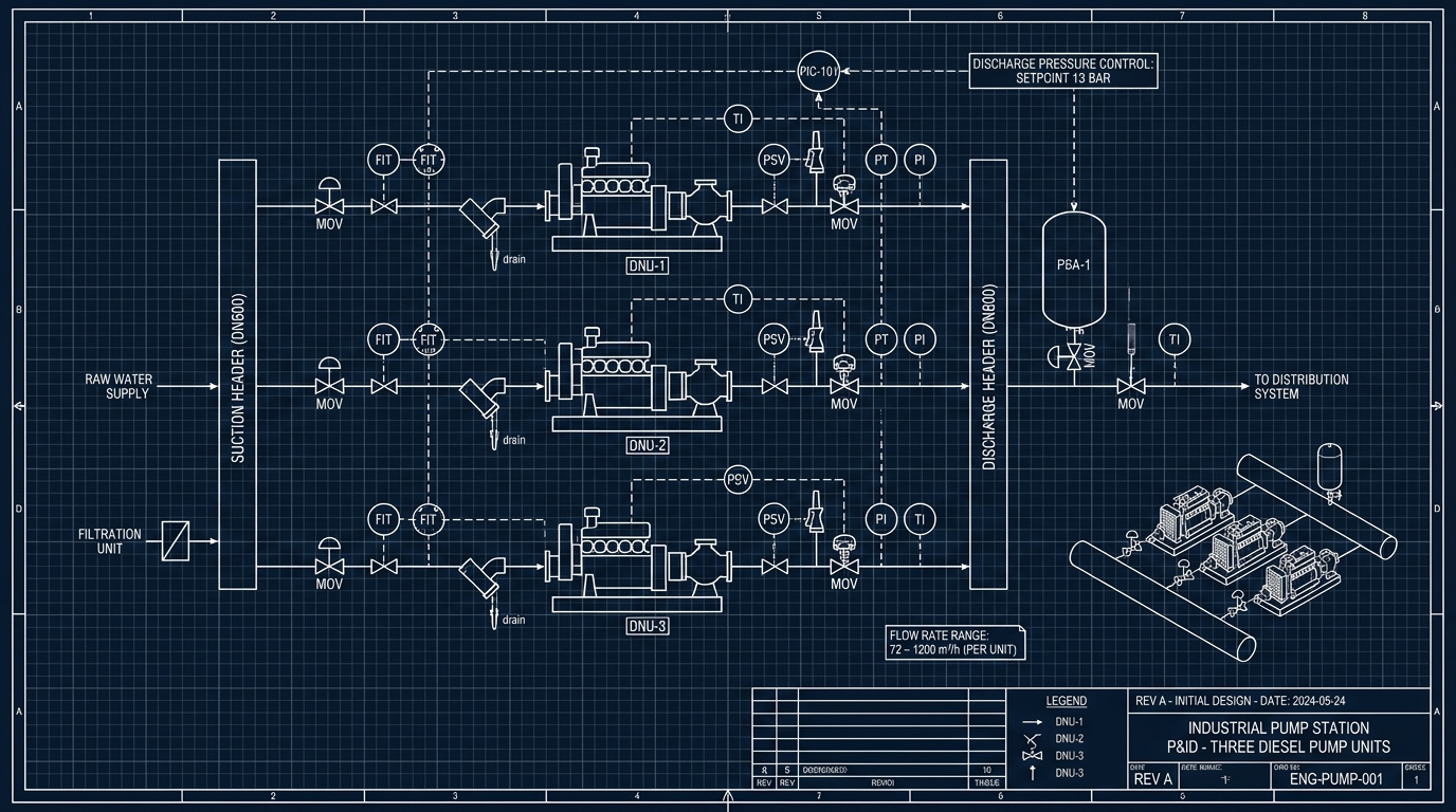




Technical P&ID (Piping and Instrumentation Diagram) blueprint according to ISA-5.1 and ISO 14617 standards for a Hydraulic Test Pumping Station with 3 parallel Diesel Pumping Units (DPU 1, DPU 2, DPU 3). Clean CAD blueprint style with white background, sharp vector line weights, precise ISA instrumentation bubbles, and structured legend. Key corrections and elements included: 1. Diesel engines driving pumps are sequentially tagged: DE-01 (DPU 1), DE-02 (DPU 2), and DE-03 (DPU 3). Coupled to Forcia MH400-130 centrifugal pumps. 2. Suction lines from Well No.2 have compound vacuum/pressure transmitters tagged strictly as PT-02 (DPU 1), PT-03 (DPU 2), PT-04 (DPU 3), with ISA bubbles showing PT/PI. Suction line includes DN250 foot valve with strainer, flat-top eccentric expander DN250 to DN300, DN250 butterfly valve with limit switches (ZSC/ZSO 08, 09, 10), flat-top eccentric reducer DN300 to DN200, and flexible compensator. 3. Discharge common header DN500 (PN16) with master pressure transmitter PT-01 (0-25 bar). Discharge of each pump features check valve DN200 and flow switches FS-05, FS-06, FS-07. 4. Recirculation bypass line DN200 with modulating control valve tagged consistently as PCV-01 (no duplicate tags) discharging into Well No.1 with 90-degree submerged elbow against the wall. 5. Auxiliary vacuum priming unit (Eifel EJT3) with pressure transmitter PT-05 (0-1.5 bar) on its main shared discharge line before branching. Priming lines connect directly to pump suction sections strictly AFTER the DN250 butterfly valves. 6. Central Control Cabinet (CCC) PLC with CAN-bus SAE J1939 connections to engine ECUs, well level instrumentation (LT/LI-01, LSHH-01, LSH-02, LSL-03, LSLL-04), and full technical legend in CAD engineering style.
Free to start · Generate videos and images with AI in seconds