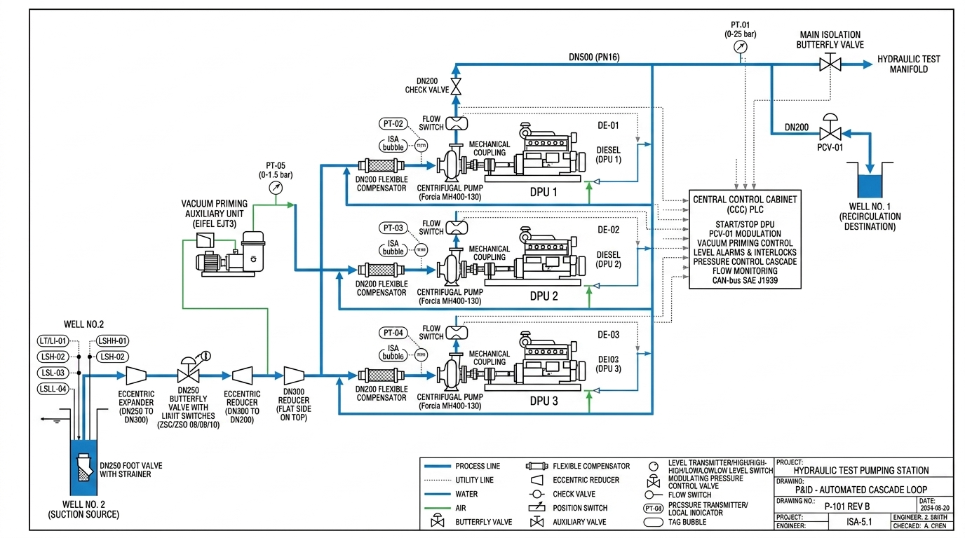


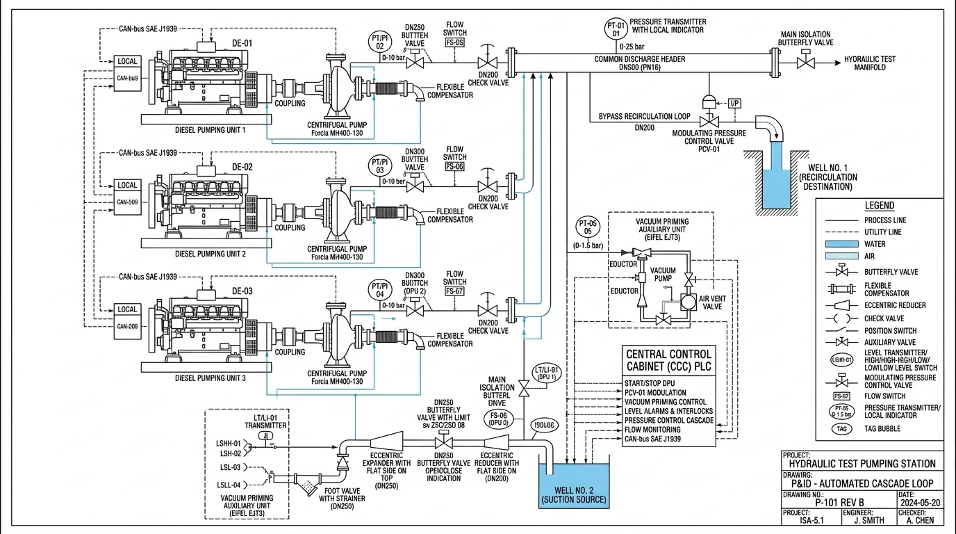
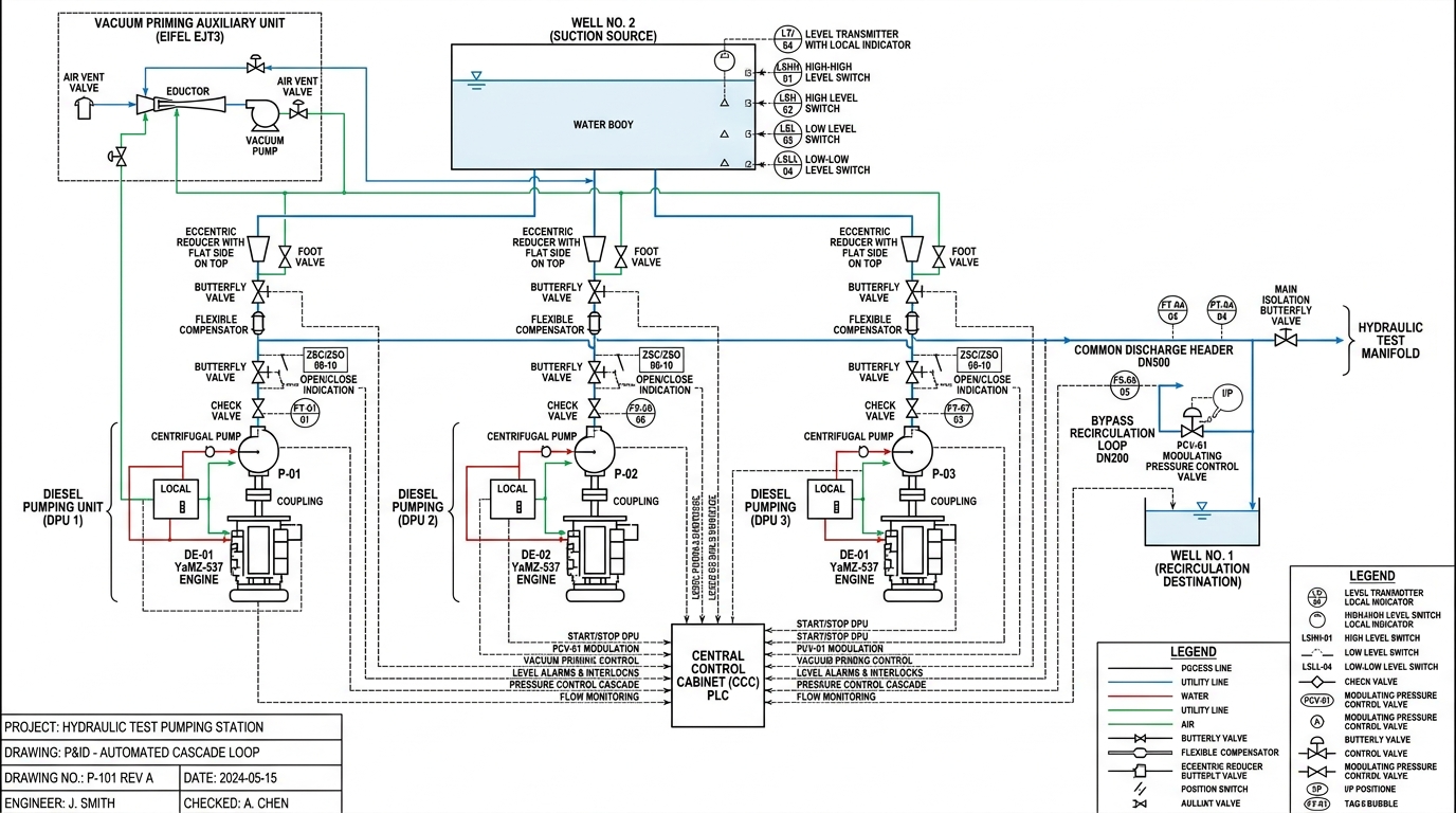

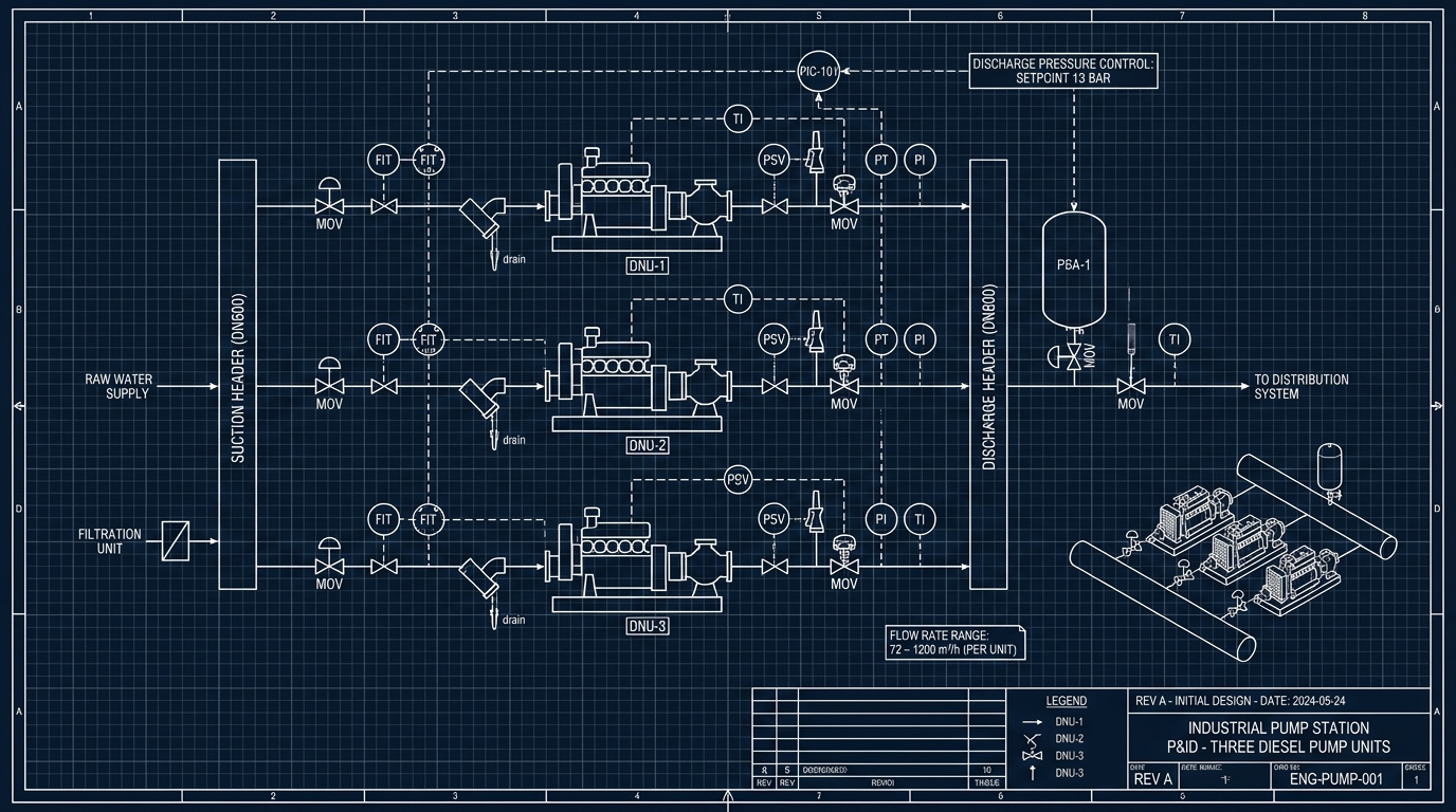






Professional CAD Piping and Instrumentation Diagram (P&ID) technical engineering blueprint conforming strictly to ISA-5.1 and ISO 14617 standards for a Hydraulic Test Pumping Station with 3 parallel Diesel Pumping Units (DPU 1, DPU 2, DPU 3). Clean white background, crisp vector lines, standard technical CAD styling. CRITICAL TOPOLOGY & INSTRUMENTATION: 1. PUMP ORIENTATION & FLOW: For all 3 pumps (Forcia MH400-130), the horizontal axial nozzle is the SUCTION INLET (bold blue line enters horizontally via DN200 flexible compensator). The top vertical nozzle is the DISCHARGE OUTLET (water exits vertically through DN200 check valve and flow switch up into the common DN500 header). 2. NO SIGNALS ON COUPLING: No instrumentation lines connect to the mechanical coupling or drive shaft between engine and pump. All dotted signal lines route cleanly to the Central Control Cabinet (CCC) PLC. 3. DIESEL ENGINES: Tagged sequentially DE-01 (DPU 1), DE-02 (DPU 2), and DE-03 (DPU 3). 4. SUCTION SENSORS: Tagged strictly as PT-02 (DPU 1), PT-03 (DPU 2), PT-04 (DPU 3) with ISA bubble 'PT/PI'. Suction line includes DN250 foot valve + strainer, flat-top eccentric expander DN250 to DN300, DN250 butterfly valve with limit switches ZSC/ZSO 08/09/10, flat-top eccentric reducer DN300 to DN200. 5. BYPASS CONTROL VALVE: Tagged consistently as PCV-01 on the DN200 recirculation line to Well No.1. 6. PRIMING SYSTEM: Vacuum priming unit (Eifel EJT3) has pressure transmitter PT-05 (0-1.5 bar) on main shared header before branching; green utility lines inject into suction pipe strictly AFTER the DN250 butterfly valves. 7. WELL NO.2: Clearly labeled 'WELL NO.2 (SUCTION SOURCE)' containing LT/LI-01, LSHH-01, LSH-02, LSL-03, LSLL-04. 8. TEXT: Crisp, professional CAD annotations with correct spelling (BUTTERFLY VALVE, FLAT SIDE ON TOP), full engineering legend and title block.
Free to start · Generate videos and images with AI in seconds